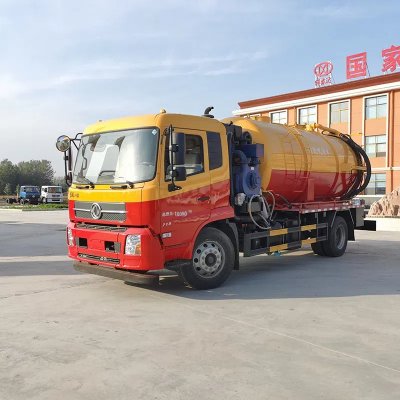
Core structure of fecal suction truck
1. High efficiency. It is reported that the three wheeled small suction truck, as a type of cleaning and sanitation machinery, has a higher cleaning efficiency compared to traditional manual cleaning methods. It has a small size, suitable for various cleaning and cleaning places, easy to use, and high efficiency.
2. Less investment. Normally, a small three wheeled fecal suction truck only requires 1-2 sanitation personnel to complete the pumping and transportation work. Greatly reduce human capital investment.
3. In line with the trend of environmental protection development.
The suction truck is mainly composed of: tank body, vacuum pump, power take-off, four-way valve, water gas separator, oil gas separator, return oil tank, directional rotating arm, and locking mechanism.
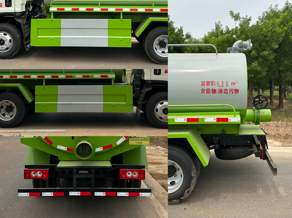
1. Tank body
The tank is the main body of the manure truck, and its top is equipped with air holes and suction and discharge holes. The air hole is connected to the water vapor separator as a channel for air to enter and exit the tank. The inlet hole is usually sealed and can be opened during maintenance. The suction and discharge hole is connected to a suction hose and a siphon channel for the entry and exit of fecal liquid from the tank.
There are platform boxes in the middle of both sides of the tank body, which are usually used to hold the suction hose and stand during maintenance. The tank is equipped with anti sway plates inside to reduce the severe shaking and impact of liquids caused by vehicle movement, which can damage the tank and its frame connection parts. The front head is equipped with an observation tube for monitoring the loading capacity and preventing overloading. There is a cleaning hole at the bottom, which is usually sealed. When cleaning the tank, the cleaning hole cover can be opened to allow the sewage to flow out naturally.
The tank is rigidly connected and installed on the frame, with a buffer pad in between to reduce damage to the tank caused by vehicle vibration.
Due to the continuous immersion of the fecal suction hose on the liquid surface, the air inside the tank becomes thinner and thinner as it cannot be replenished, resulting in a lower pressure inside the tank than atmospheric pressure. The fecal liquid is discharged from the tank through the fecal suction hose under the action of compressed air.
2. Vacuum pump
The vacuum pump of the suction truck is a key component on the suction truck, mainly used in conjunction with the power take-off, three-way four position valve, etc. to achieve vacuuming and pressurization of the tank body.
At present, single-stage rotary oil sealed vacuum pumps are commonly used on fecal suction trucks, with an ideal working pressure of 200PA-8500PA. They have the characteristics of easy installation, high vacuum degree, and high efficiency.
A vacuum pump is mainly composed of a pump body, a rotor and its components, a pump casing, rotor blades, slip rings, bearing covers, and sealing devices. The rotor is a vulnerable part, and in order to facilitate disassembly and repair, the center of rotation of the rotor deviates from the center of the pump body.
Its working principle is that the eccentric rotor works under the drive of the power take-off, sucking the tank into the compression chamber. When the pressure exceeds the specified value of the exhaust port, the compression chamber automatically opens, and the compressed air is discharged. In this way, the air inside the tank is extracted and repeatedly circulated, forming a vacuum inside the tank.
In order to ensure the normal operation of the vacuum pump and avoid pollution, oil and gas separators and water and gas separators are also installed during the production of the suction truck to filter the water vapor and oil and gas in the compressed gas.


【Technical parameters of the entire vehicle】 | |||
Product trademark | Xiangnongda brand | Announcement Batch | 372 |
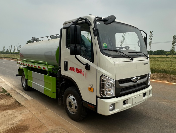
Product Name | Fecal suction truck | Product model | SGW5070GXEBJ6 |
Total mass (Kg) | 7360 | Tank volume (m3) | 5.25 |
Rated load capacity (Kg) | 4000 | Dimensions (mm) | 5995×2100,2050×2500,2450 |
Curb weight (Kg) | 3165 | Cargo compartment size (mm) | ×× |
Rated passenger capacity (person) | Total mass of quasi trailer (Kg) | ||
Cab capacity (persons) | 3 | Maximum load capacity of saddle (Kg) | |
Approach Angle/Departure Angle (degrees) | 21/14 | Front suspension/rear suspension (mm) | 1130/1505,1100/1535 |
Axle load (Kg) | 2640/4720 | Maximum speed (Km/h) | 95,108 |
remarks | The side rear protection is welded with Q235 material, and the cross-sectional size of the rear protection (mm) is 100 × 50. The height of the rear protection above the ground (mm) is 390. This vehicle is used for collecting and cleaning feces and sewage, and the main devices are the tank and pump Transport medium: liquid waste, medium density: 800 kg/cubic meter The total volume of the tank is 5.25 cubic meters, and the effective volume is 5.0 cubic meters The tank size is (length x long axis x short axis) (mm): 3600 × 1650 × 1150. The ABS system controller model is CM4XL-4S/4M, and the ABS system controller manufacturer is Guangzhou Ruili Kemi Automotive Electronics Co., Ltd Optional new front grille and logo, optional front panel with decorative words "Foton · Navigation", Expand the front bumper style and optional front bumper style | ||
【Chassis Technical Parameters】 | |||
Chassis Model | BJ1076VEJDA-51 | Chassis name | Truck chassis |
Trademark name | Futian brand | manufacturing enterprise | Beiqi Foton Motor Co., Ltd |
Number of axes | 2 | Number of tires | 6 |
Wheelbase (mm) | 3360,2800 | ||
Tire specifications | 7.00R16LT 14PR,7.50R16LT 12PR,7.50R16LT 16PR | ||
Number of steel plate springs | 3/6+6 | Front wheel base (mm) | 1550,1575,1585,1600 |
Fuel type | diesel oil | Rear wheel base (mm) | 1485,1590,1605,1455,1525 |
Emission standards | GB17691-2018 National VI | ||
Engine model | Engine manufacturing enterprises | Emissions(ml) | Power (Kw) |
Q25A-150E60 | Anhui Quanchai Power Co., Ltd | 2496 | 110 |
3. Power take-off device
The operation of the suction truck power take-off relies on engine power passing through the power take-off and transmission shaft to rotate. The power take-off is installed on the left or right side of the transmission, and the upper part of the operating handle is located on the middle plate of the cab.
This type of power take-off consists of an input gear, an input shaft, an intermediate gear, an intermediate shaft, an output shaft, an output gear, a fork shaft, a fork, and an operating handle.
The input gear and the output gear of the transmission are a constant meshing pair. Before starting the vacuum pump, ensure that the output gear of the transmission is a constant mesh pair. Before starting the vacuum pump, shift the transmission to neutral, then start the engine, disengage the clutch, and turn on the power take-off switch. At this time, the fork shaft moves forward, and the fork drives the output gear to slide on the output shaft and mesh with the intermediate gear. The output shaft is transmitted to the input gear through the spline and the output gear, and the intermediate gear is transmitted to the output gear, which is then transmitted to the transmission shaft through the output coupling. Thereby driving the vacuum pump to rotate.
4. Four way valve
The vacuum pump can only rotate counterclockwise (facing the front of the car). To suck in air from the tank or discharge air into the tank, a four-way valve is required.
The four-way valve is respectively connected to the tank, vacuum pump, and return oil tank for atmospheric communication. There is a partition inside the four-way valve. Change the suction direction of the vacuum pump, and when the four-way valve connects the tank to the vacuum pump, the manure truck will begin the discharge operation.
5. Water gas separator
The water vapor separator is located at the top of the front of the tank, and the rear is connected to the tank. It is equipped with gas delivery pipes inside, and rectangular holes are opened on both sides of the pipes for air to enter and exit the storage tank. During the suction operation, the air in the container suddenly expands in volume and the flow rate decreases when it comes out of the rectangular hole. The number of heavy water molecules decreases, which can reduce their harm to lubricating oil and machinery.